Multiscale Modeling of Hall Thrusters

One of the topics we specialize in is the study of electric propulsion, or EP for short. Electric propulsion is the name used to describe the types of spacecraft motors that use electricity to produce thrust. Conventional chemical rockets generate thrust by burning some propellant (such as kerosone or hydrazine). EP devices on the other hand either use electricity to heat and hence expand some working gas, or use electromagnetic forces to accelerate ionized gas, or plasma.
There are many types of EP devices. One of the most attractive ones for station keeping and orbit transfers are so called Hall Effect Thrusters (HET), or just Hall thrusters for short. Hall thrusters consist of a chamber that is open to the ambient environment on one end. The opposite end is capped by the anode that also serves as the inlet for the propellant gas. A cathode located outside the thruster produces electrons. Some of these electrons flow into the channel and towards the anode and on their way ionize the propellant gas. In order to increase their transit time (electrons are very light and hence very fast) and thus increase the ionization efficiency, a magnetic field is applied across the channel. Magnetic field acts as a sort of a friction field – it becomes much easier for the electrons to move along the field lines than across them.
In the presence of magnetic field, charged particles begin orbiting about the magnetic field lines (similar to our vxB motion example). The magnetic field strength in Hall thrusters is selected such that only electrons are magnetized – the orbit diameter for ions is much larger that the dimension of the thruster. The only way the electron can move across the field line is if some event, such as a collision with an atom, disturbs its circular motion. It is this cross-field transport that is of much interest to the EP community. Despite Hall thrusters having over 40 years of flight heritage, the details of just how electrons move from the cathode to the anode is still not fully understood. The total diffusion rate due to “known” events such as collisions and wall interactions does not correlate with the anode currents measured experimentally. The real cross-field mobility of electrons is much higher than can be explained using the classical models. This unexplained source of electron transport is called anomalous diffusion.
Of course, there is nothing anomalous about this process – the problem is that current models do not capture it well. Several different researchers have written codes to study these devices (see the accompanying paper, IEPC-2011-11 for more). Due to computational reasons, it is not practical to model electrons as particles. Instead, the most common types of Hall thruster codes assume that several important electron properties stay constant along a magnetic field line. Electron propertied can then be determined by solving 1D conservation equations across magnetic field lines. An analytical formula is used to calculate the mobility based on the local density of ions and neutrals, as well as the strength of the magnetic field.

Figure 1. Schematic of our multiscale model. Kinetic code is used to determine mobility self-consistently along multiple magnetic field lines. Mobility is used in an axisymmetric hybrid code. Ions exiting the thruster are used to obtain discretized velocity distribution function that can act as a source for a plume model.
The problem with this approach is that transport is inherently a kinetic process. Fully kinetic Hall thruster codes have also been attempted, but these generally require supercomputers to run – and that’s even after some tricks are played with physics to make the codes run faster. For this reason we started working on a multiscale approach to modeling Hall thrusters. The idea is to divide the entire problem set of a thruster operating on a spacecraft into three spatial scales.
- Magnetic field line: On the scale of a single field line, the physics is dominated by the electron spiral motion about the field line. Ions and neutrals can be assumed to remain frozen. By kinetically modeling the electrons, we can determine transport self-consistently.
- Thruster Channel: On the scale of a thruster channel, electrons can be assumed to be thermalized along a field line and hence a quasi-1D fluid approach can be used to model the electrons. Ions and neutrals are treated kinetically to capture deviation from Maxwellian velocity distribution function. Mobility computed in step 1 is used in the electron equations.
- Spacecraft: On the scale of a spacecraft, magnetic field plays a negligible role, and expansion of the plasma plume is due to electrostatic forces. Of interest here is the expansion of the charge-exchange wing and its contamination impact on spacecraft components. To model the thruster, ions exiting the simulation in step 2 are sampled to obtain a discretized velocity distribution that acts as a source for our plume model.

Figure 2. Close up of the computational domain for the axisymmetric code. The computational mesh on which the electron equations are solved is highlighted.
This entire process is described in more detail in the IEPC-2011-11 paper written for the upcoming 32nd International Electric Propulsion Conference in Wiesbaden, Germany. This approach has the benefit that each code can be written specifically to study the physics at hand, thus reducing total computational time. We utilized a different simulation code for each aspect of our model. We have developed a kinetic code called Lynx to simulate the motion of electrons about a magnetic field line. We are in the process of developing a general 2D plasma simulation code that will be able the thruster discharge in step 2. Lynx will naturally tie into Starfish, making the iterative process seamless. However, this work is still ongoing. In this feasibility study we instead utilized an industry-standard code for modeling Hall thrusters, HPHall, to model the thruster discharge. HPHall was modified to interact with the Lynx code, and to also sample particles exiting the thruster. A 3D electrostatic plume code Draco was used to model the thruster plume.
Figure 1 shows the conceptual diagram of our approach. Steps 1 and 2 depend on each other, and hence to obtain a fully consistent answer, these steps need to be iterated. We did not do so at present. This step is left as future work, to be completed after our 2D code Starfish is released. Figure 2 shows the schematic of the thruster studied in this paper. The approach was applied to the Princeton 2.6 cm cylindrical Hall thruster. This figure also shows the computational domain used by HPHall, and the extent of the magnetic field line mesh used to computed the electron properties. Figure 3 shows an example of typical properties along a magnetic field from the kinetic code. The electron density is seen to follow the ion density (which is assumed frozen), leading to quasineutrality in the bulk plasma.
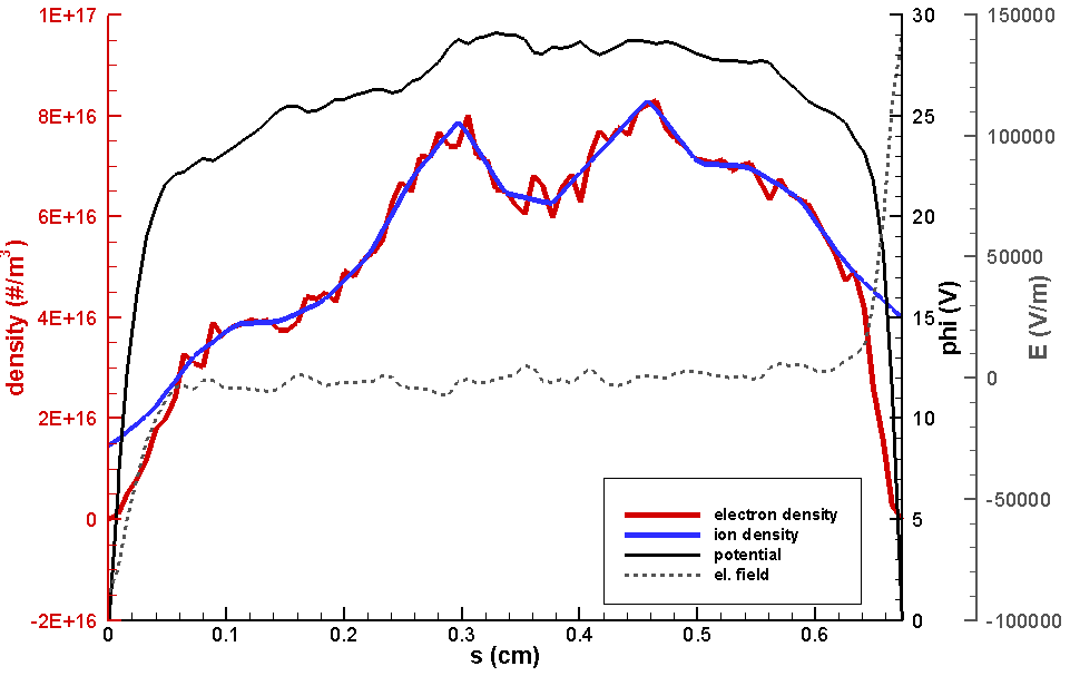
Figure 3. Typical results from the kinetic code. The electrons are seen to follow the ion density in the bulk region, and clear sheath forms along the two walls.
Finally, Figure 4 compares the mobilities from the analytical model used by HPHall (left) to the one determined kinetically. It should be pointed out that mobility is not computed on the right most magnetic field line in HPHall due to this line acting as a boundary condition. The jagged feature on the second to right line is due to interpolation artifacts. Significant variations between the two variations can be seen. While in the analytical model, mobility follows the magnetic field strength, the kinetic mobility instead consist of several regions of increased mobility and intermediate region of reduced mobility. The left band is thought to correspond to a high emission of secondary electrons from the wall, and thus high near wall conductivity (NWC). The right band is due to a large electric field since this line corresponds to the start of the acceleration zone. Our numerical results are compared with experimental measurements in Figure 5. The dashed line shows the results obtained with the analytical mobility, while the solid line uses the mobility map obtained from the kinetic code. The kinetic approach is seen to improve the correlation with experimental potential measurements. The potential is seen to increase monotonically towards the anode, instead of containing a “hump” that could result in some ions flowing in the opposite direction. We hope that the results can be improved further by iterating the two codes. This remains as future work.


Figure 4. Comparison of the mobilities. On the left is the mobility computed using the classical model. On the right is the mobility obtained from the kinetic code.
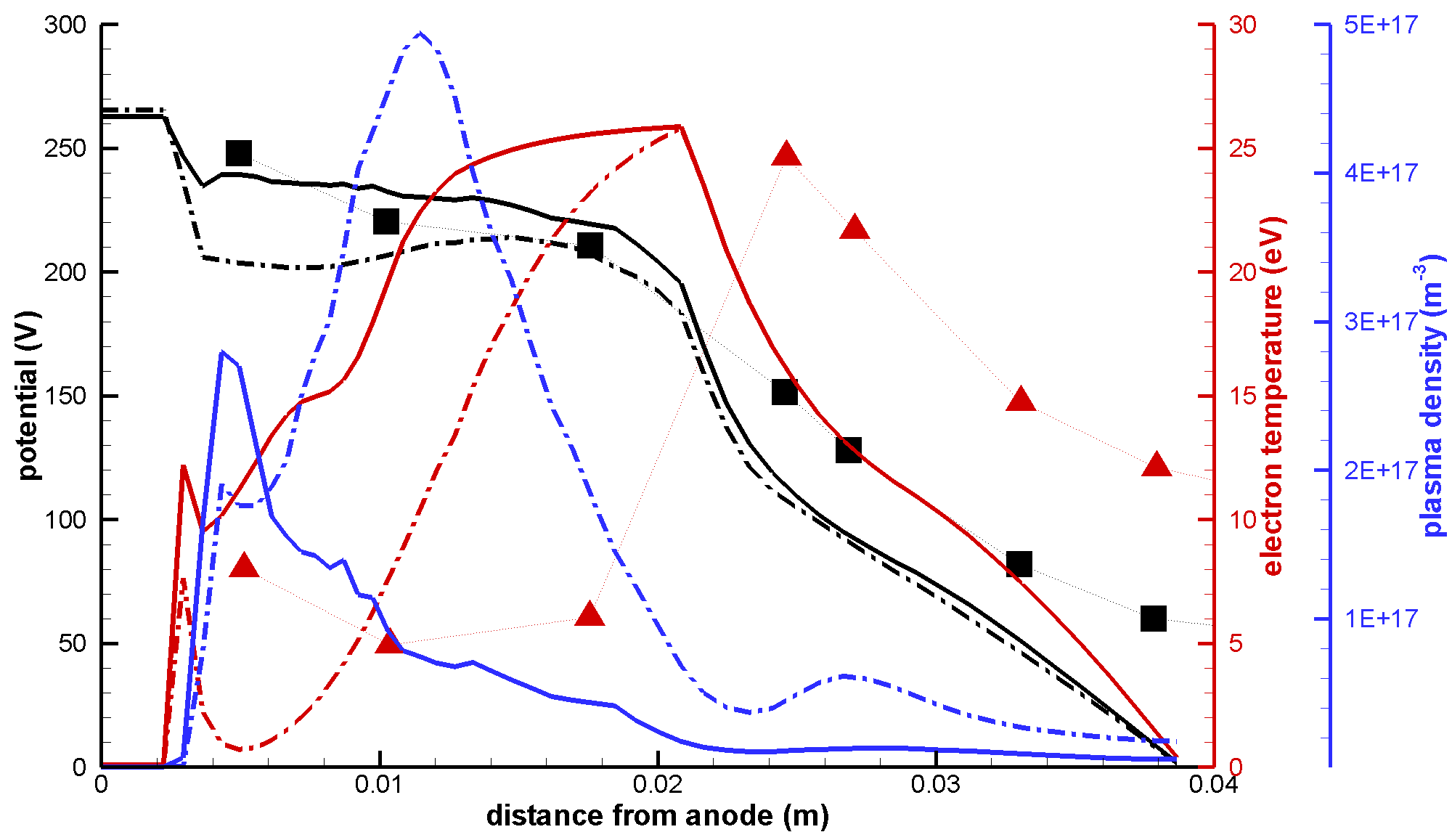
Figure 5. Comparison of axial properties with experimental data. Results with the analytical mobility are shown with the dashed line, while solid line is used to show the results with the kinetic data. Markers indicate measurements. (Click on the image for larger version)
Download the entire paper here: IEPC-2011-11.pdf (2Mb). The paper also discusses aspects of the plume model.
Keep me updated please I’m interested in this thanks
I can’t tell you that I understood most of it but I enjoyed reading about this bit of chemistry regarding spacecraft and ways of propelling them. I did not know you were in this field of work. You really have to have a head on your shoulders! Interesting and exciting work you do !
Hello,
Interesting, is this simulation code available for commercial . We are interested to sell this in India. Please let me know.
Thanks,
Hari Krishna
i am sukhmander from IIT Delhi research scholar from India. WE ARE LOOKING TO PURCHASE PIC CODE TO SIMULATE TO PHYSICS OF HALL THRUSTER.PLEASE TELL US ABOUT THE DETAIL OF THE COST AND LATEST VERSION AVAILABLE FOR THE SAME
Helo sir,
I am also a phD RESEARCH SCHOLAR IN IIT DELHI,CENTRE FOR ENERGY STUDIES. My research work is related to RF plasma heating and want to do some simulation through PIC tool but i need a discussion basically to get an idea of how to proceed further. Please, it would be a great gesture if you could just give a bit of ur precious time sir.
Kindly leave a mail iff at all u can guide.
Thanking you
Regards
Arti Rawat
Parts and uses in figures 1 & 2 need more annotation. Thank you for this.G