Initial Progress on Micro Cathodic Arc Thruster Plume Simulations

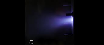
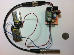
Few weeks ago I started working on modeling the near plume of a micro cathodic arc thruster (µCAT) that is currently being investigated at the George Washington University. You can see images of the thruster below. The thruster consists of a ring-type Titanium cathode, an insulator, and a copper anode. An inductor-based power supply provides pulses that result in vacuum arc breakdown at the cathode/insulator interface. This breakdown results in formation of dense Titanium plasma from the cathode spot.
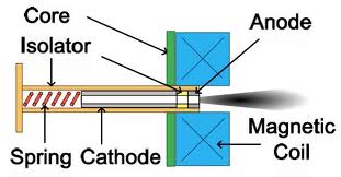
In the absence of additional forces, the ion velocity is expected to be primarily in the radial direction. In order to turn the ions into the axial direction to provide thrust, the thrust tube is surrounded by an electromagnet that produces magnetic field lines predominantly parallel with the thrust axis. The magnetic field is selected such that only the electrons are magnetized. The resulting ambipolar field then provides the acceleration that rotates the ions in the thrust direction. The magnetic field further allows the mission designer to tune the trust and Isp by adjusting the field strength. The magnetic field also assists with uniform erosion of the cathode.
Simulation Setup
The miniature size and power requirements of the thruster make it an attractive choice for nanosatellite missions that historically had to manage without using propulsion. However, before the thruster can be flight qualified, it is necessary for us to obtain a better understanding of performance, plume properties, and any possible backflow contamination concerns. The small size makes it difficult to utilize standard tools such as Langmuir and Faraday probes. The experimental effort to data, which has been summarized in number of papers, has mainly consisted of using a segmented disc to measure current density, a gridded probe to study ion velocity, and microbalances to determine thrust and mass flow. Numerical simulations can help us fill in the gaps. Due to its small size, we should be able to perform a single end-to-end simulation encompassing the internal region and extending to the near plume. That is the objective of this study.
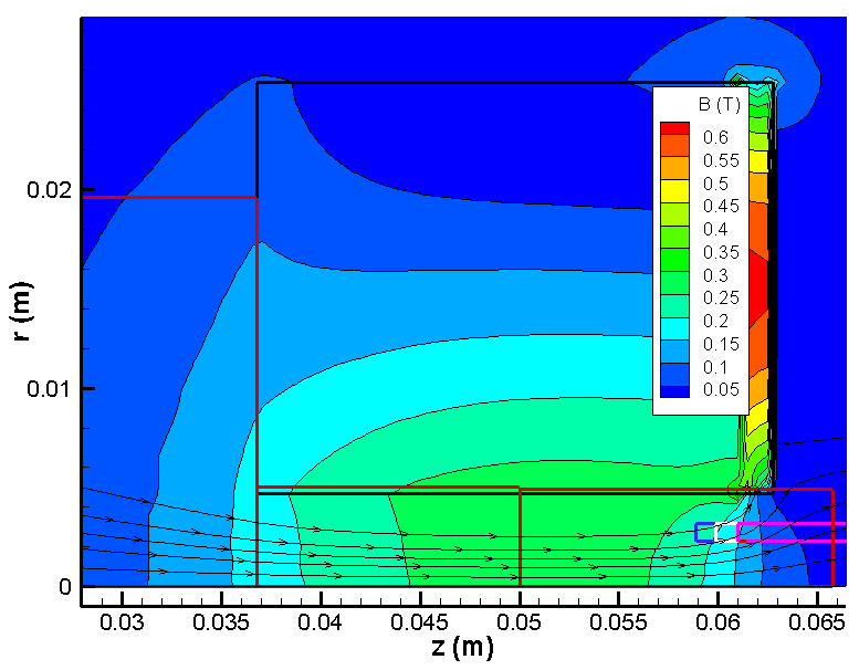
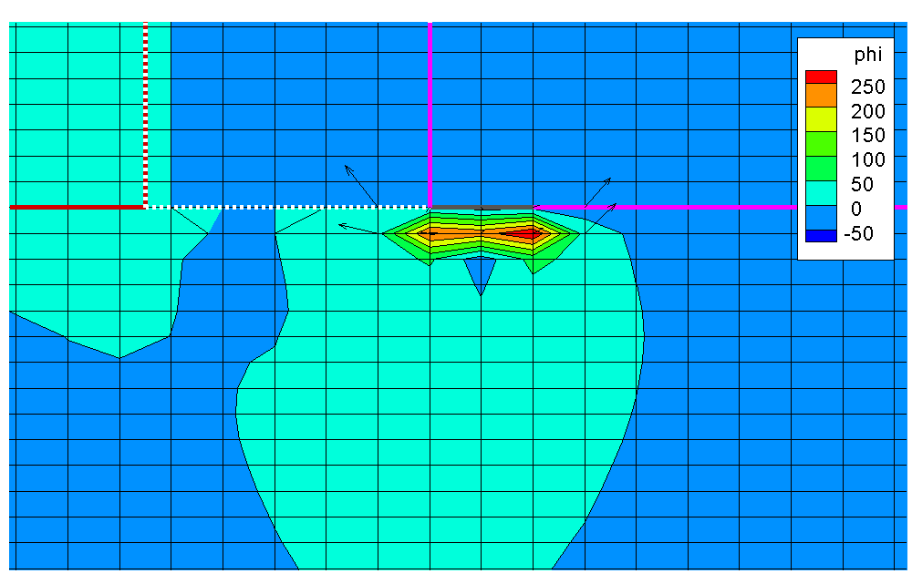
Figure 3 shows the planned simulation domain. It consists of three rectilinear meshes of varying node spacing. The cathode is shown in pink, the insulator is in white, and the anode is in blue. The black square is the magnet. The three meshes are shown by the red outlines. We perform the simulations with our Starfish code. Starfish supports both kinetic and fluid materials. In this case we opted for the fully-kinetic approach in which ions and electrons are simulated as macroparticles. This then requires a mesh fine enough to resolve the local Debye length. This however turned out to be a challenge. Starfish for now contains just a Gauss-Seidel based matrix solver, and as you surely know, the Gauss-Seidel schmee require a large number of iterations to converge. Given that some 250,000 time steps were used to generate the plots below, the convergence rate of the solver is a huge contributor to the simulation computational performance. Unfortunately, in the absence of resolving the Debye length, a virtual anode forms as shown in Figure 4. This is a common occurrence in kinetic plasma simulations and is due to the mesh not resolving local charge non-neutrality. The electric field induced by the numerical artifact forces the ions back towards the cathode spot and we do not obtain a discharge.
Preliminary Results
We tried several approaches and finally settled and using an artificial permittivity multiplier. Since $latex nabla^2 phi = -rho/epsilon_0$, increasing vacuum permittivity is analogous to a decrease in the plasma density. And since Debye length scales inversely with the density, this then allows us to use a coarser grid. Below you will find videos from our preliminary results. These concentrate only on the near cathode region. The results still need to be analyzed in more detail, but they at least show the simulation capturing some of the basic physics.
Ion and Electron Density without Magnetic Field
First, we can see that in the absence of the magnetic field, the ions and electrons indeed initially flow in the radial direction. Because our simulation is axisymmetric, we are actually modeling a uniform circumferential source. The resulting growth of density near the centerline results in formation of a repulsive electric field which acts to shed this ion concentration. The electrons can be seen to closely follow the ions in this case.
Ion and Electron Density with Magnetic Field
The situation is quite different once the magnetic field is included. As we can see below in the electron animation, electrons are now confined to a thin tube corresponding to a magnetic field line. Collisions were ignored in this simulation and hence the electron motion is restricted to the tangential direction. The ions can be seen to initially flow radially just as in the case above, however, they can be seen to turn and roughly follow the electrons. We can see that only about 50% of the ions actually flow in the correct direction. The other half flows upstream due potential drop induced by the cathode. It is not yet clear whether this is the true behavior or a simulation artifact due to perhaps incorrect boundary conditions. However, what is reassuring is that, the experiments indicate that only about 50% of the ion current leaves the thruster with the second half depositing back in the device. We can also see that a periodic instability develops. The source of this instability is still under investigation.